Now before using processing, we done the last arduino code wich was a bit more complex that the others. Here we made a RBG led to give different colors depending of the light that recives a LDR, and the reproduce a sound too
Apart from all the materials used for the other stuff, we now will use a RBG LED, a LDR resistor and a buzzer

For this, we've used the following code which I will explain how it works:
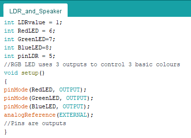
First we do the same as always. We will say to the code where is located everything, every single entrance of the RBG LED and the LDR resistor, and the in the setup explain that every color of the RGB (red, green and blue) are OUTPUTS
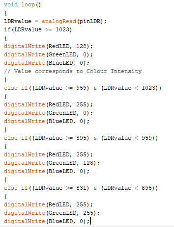
Here I will explain the void loop, which is quite long but actually simple. Here we will just put lots of values depending of how we want to make the RBG LED color to change in every point of intensity of the LDR resistor, here in the photo there isn't everything, but you actually need to set up all the intensity to have different colors in lots of points of the intensity of the LRD resistor, depending of what you want using in the RGB color system, which consist in setting a value from 0 to 255 (depending of the intensity) in the value of red, blue or green, and mixing this will make all the rest of colors
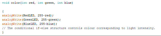
Then to finish we create color, which will be a variable that will help in the "else if" structure used in the loop, that controls colour depending of the light intensity
Now to finish making the code work, we will connect everything to the chip similar to the scheme of below, and then run the code
